
OSI introduction (Part 1)
This is first post in OSI series. A motivation for this series is to provide a comprehensive guide to OSI model. In this post we will introduce OSI model as a whole and in the next posts we will dive into each layer in more detail.
I will try to keep it simple and easy to understand. Of course, if you have any questions, feel free to join our community and ask them.
What is OSI model?
OSI model is a conceptual model that standardizes the functions of a telecommunication or computing system into seven abstraction layers. Each layer is responsible for a specific function and communicates with the layers above and below it.
The model was developed by the International Organization for Standardization (ISO) in 1984. The goal was to create a standard for how different systems could communicate with each other.
Why OSI model?
OSI is not a physical model, but a logical one. That means it doesn’t describe how data is transmitted over a network, but rather how it should be transmitted. It provides a framework for understanding how different networking technologies work together.
Quite often OSI model is being compared to TCP/IP model. The main difference between them is that OSI model is a theoretical model or framework, while TCP/IP model is a practical implementation of OSI model.
We will cover TCP/IP model and how it differs from OSI model in the next series.
OSI layers
On the image below you can see basic overview of OSI model.
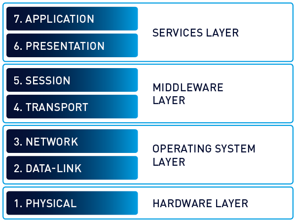
OSI model consists of seven layers. Each layer has a specific function and communicates with the layers above and below it. Here is a brief overview of each layer:
-
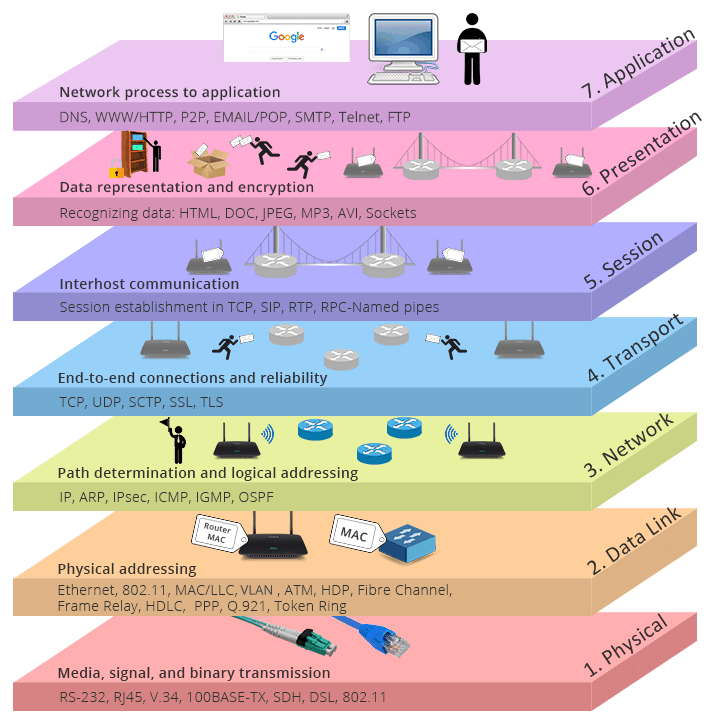
The Application layer (Layer 7): This is the top layer of the OSI model, this layer serves as the window for application services. Layer 7 is not the actual application, but rather the channel through which applications communicate.
-
The Presentation layer (Layer 6): This layer is responsible for data translation and encryption. It ensures that data is readable by the application layer. The presentation layer is responsible for items such as:
- Encryption and decryption of messages
- Compression and expansion of messages, format translation
- Handling protocol conversion
-
The Session layer (Layer 5): Its purpose is to allow two applications on different computers to establish and coordinate a session. It is also responsible for managing the session while information and data are being moved. When a data transfer is complete, the session layer tears down the session.
-
The Transport layer (Layer 4): This layer is responsible for end-to-end communication. It ensures that data is transferred reliably and without errors. Whereas the application, presentation, and session layers are primarily concerned with data, the transport layer is focused on segments.\
- On the sending side, it takes data from the session layer and breaks it into segments for the network layer.
- On the receiving side, it reassembles the segments from the network layer and passes them on to the session layer.
Depending on the application protocol being used, the transport layer can send data either quickly or reliably. Transport layer responsibilities include end-to-end error recovery and flow control. The two primary protocols found on this layer include:
- TCP: A connection-oriented protocol; provides reliable communication using handshaking, acknowledgments, error detection, and session teardown
- UDP: A connectionless protocol; offers speed and low overhead as its primary advantage
-
The Network layer (Layer 3): This layer is responsible for routing packets from the source to the destination.ts. The network layer is the home of the IP, which offers the best effort at delivery and seeks to find the best route from the source to the target network. The layer is responsible for:
- Logical addressing
- Routing
- Path determination
- Packet forwarding
- Error handling
Network-layer components include:
- Routers
- Stateless inspection/packet filters
-
The Data Link layer (Layer 2): This layer is focused on traffic within a single local area network (LAN). The data link layer formats and organizes the data before sending it to the physical layer. It uses media access control (MAC) processing for flow control and multiplexing between two systems. It also uses logical link control (LLC) to provide flow control and error control. The data link layer organizes the data into frames. When a frame reaches the target device, the data link layer strips off the data frame and passes the data packet up to the network layer. Data-link-layer components include:
- Bridges
- Switches
- Network Interface Cards (NICs)
- Media Access Control (MAC) addresses
-
The Physical layer (Layer 1): Bit-level communication takes place at layer 1. Bits have no defined meaning on the wire; however, the physical layer defines how long each bit lasts and how it is transmitted and received. Physical layer components include copper cabling, fiber cabling, wireless system components, and Ethernet hubs.
These layers are base of OSI model. It worth mentioning that each layer has its own protocols and standards. In the next posts we will dive into each layer in more detail.
But also it would be wrong not to mention that some specialists willing to extend OSI model with additional layers. I am going to show you one of the most popular extensions.
Bruce Schneier and the company RSA Security LLC invented the concept of layers above the OSI layer.
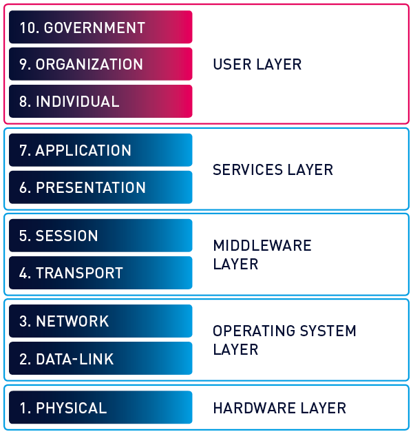
We won’t cover these layers in this series, but it’s good to know that there are different approaches to OSI model.
That’s it for this post. In the next post we will dive into the Application layer. Stay tuned!